
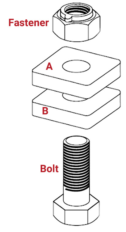
A standard bolted joint consists of four parts: a fastener, object A, object B, and a bolt.
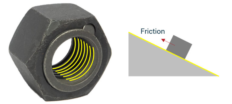
The threads on a nut, unraveled, are an inclined plane that uses leverage to do work. The force of friction keeps the nut from backing off of the bolt if designed and installed properly.
When fastened, the bolt is stretched (just a little) to create clamp force. This is called elastic stretching.
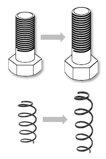
Elastic stretching provides tension in a bolted joint. A bolted joint that looks tight may be only at its elastic origin and not fully clamped. When a nut is over-tightened, the bolt can stretch beyond the elastic limit and become permanently deformed. The final fractional turn of the nut can be the difference between virtually no tension and maximum designed tension.
Real-World Example
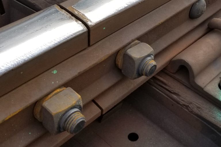
1″ diameter, 6″ clamp distance, 8 threads/inch bolted joint that may be seen on a railroad track joint bar.
Applying 908 ft-lbs of torque to turn the final 51.8 degrees stretches the bolt elastically just 0.018″ to achieve the designed 54,500 lbs of clamp force.
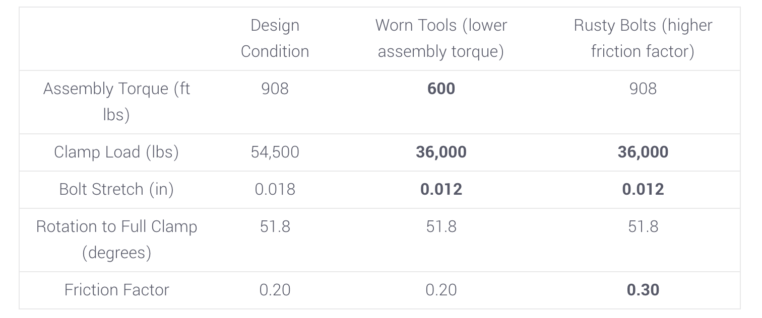
Now, reducing the application (assembly) torque from 908 to, say, 600 ft-lbs (as is seen in the field with worn tools). The stretch has fallen to 0.012″ and the clamp load is down from 54,500 lbs to 36,000 lbs. This makes the bolted joint more susceptible to loosening and fatigue failure.
Lastly, a rusty bolt may increase the friction factor from 0.2 to, say, 0.3. Still applying the recommended 908 ft-lbs, the clamp load when tight is only 36,000 lbs.
Definitions
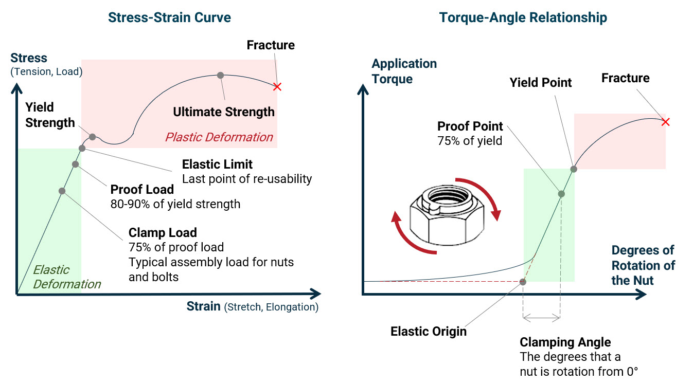
Torque-Angle Graph
Application torque = torque applied during application (measurable with a torque gauge)
Rotation to full clamp = degrees from zero that it takes for a bolted joint to go from its elastic origin to the proof point
Elastic origin = the point where elastic stretching begins
Yield point = the point where the bolt begins plastic (permanent) deformation
Proof point = 80-90% of the way to the yield point
Stress-Strain Graph
Stress = tension or load on the bolt
Strain = stretch or elongation of the bolt
Elastic stretching/deformation = stretching of a material that does not result in permanent distortion of the material
Plastic deformation = permanent deformation without fracture
Ultimate strength = maximum stress/strain a bolt can withhold before failure
Clamp load/ clamp force = 75% proof load, optimal load for bolted joints
Elastic limit = point where plastic (permanent) deformation begins
Fatigue failure = progressive propagation of cracks caused by cyclical loading (vibration) that eventually causes fracture
Other
Cyclical loading = repeated stresses or strains (often below strength of the bolt, but still causes failure over time)
Outer diameter = diameter to outermost thread crest (used most commonly for diameter)
Pitch = distance between each thread crest (measured in threads per inch)
Clamp distance = distance between contact surfaces